Posts

Image
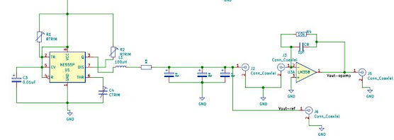
 LCR-Meter- Auto balancing bridge In the previous post signal generator is implemented using 555 timer. The next extension for this is to find impedance of the DUT using self balancing bridge method. It includes Opamp, which is used for converting current to voltage through the DUT. By comparing the output and input reference voltage from signal generator the impedance of the DUT can be estimated. Note: The design files are in kiCAD and can be found in my github profile: https://github.com/Hrishikeshkunchepu

Arduino-Spectrum-Analyzer- Part1: Sine Wave generator

Image
Step 1 of this project is to create a variable frequency generator. This can be used as test signal for the forth coming projects. Below there is circuit diagram for the variable frequency generator using 555 timer. With the resistors R1, R2 and capacitor C2 the desired frequency can be set.   Notes:  LM324 is not included in LTspice. It has to be manually edited using text editor and included opamp2. Converting pulse to square wave The output waveform of the 555 timer initially will be a pulse. With ON state being 2/3Vcc and OFF state being 0. The nature of Pulse is that it is combination of sine waves as shown below. The primary peak is followed by harmonics. A pulse wave can be converted to Sine wave using a low pass filter and terminating all high frequency harmonics. The circuit diagram is given below where a low pass filter can be implemented using Inductor and Resistor in series and three decoupling capacitors. The frequency spectrum follows it and the reduction of high frequenc